English
 Español
 Português
 русский
 français
 日本語
 Deutsch
 Tiếng Việt
 Italiano
 Nederlands
 ไทย
 Polski
 한국어
 Svenska
 magyar
 Malay
 বাংলা
 Dansk
 Suomi
 Pilipino
 Gaeilge
 عربى
 norsk
 اردو
 čeština
 Ελληνικά
 Українська
 فارسی
 தமிழ்
 తెలుగు
 नेपाली
 Burmese
 български
 ລາວ
 Latine
 Қазақ
 Azərbaycan
 slovenský
 Македонски
 Lietuvos
 Eesti Keel
 Română
 Slovenski
 Српски
 Afrikaans
 Беларус
 Монгол хэл
 O'zbek
 Sundanese
 Javanese


Product Description
Introduction of NFPA 855 Gas Detection Requirements for Battery Energy Storage
NFPA 855 mandates continuous flammable‑gas monitoring for battery energy‑storage systems (BESS). Hydrogen, released during battery thermal‑runaway venting, represents a major explosion hazard for energy‑storage containers and cabinets. The standard requires gas‑detection systems to trigger alarms and emergency ventilation before hydrogen reaches 25 % LEL, the critical safety threshold for ESS installations.
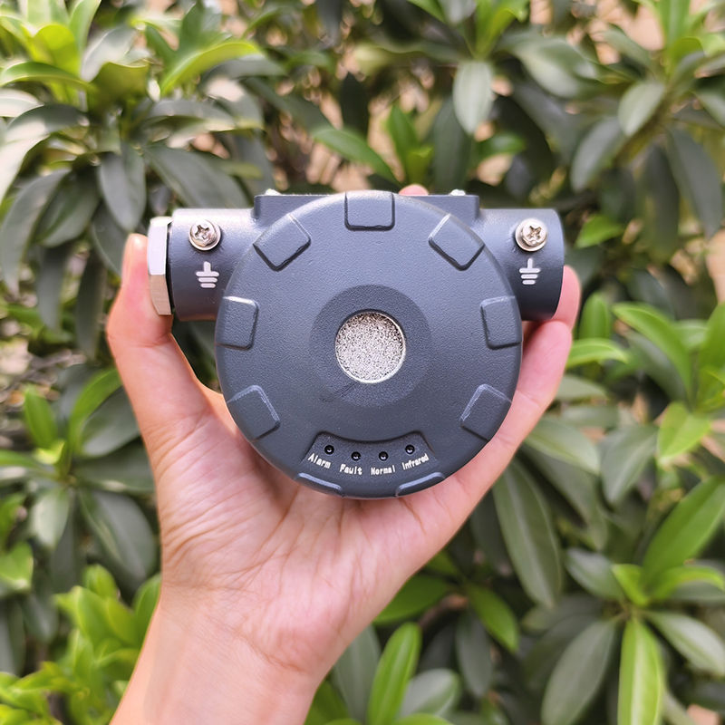
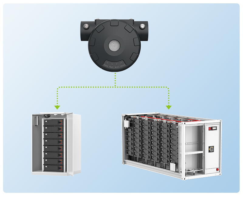
The CGT‑H2100 hydrogen gas detector is purpose‑built for battery‑energy‑storage scenarios, complying with core NFPA 855 gas‑detection objectives. This explosion‑proof, diffusion‑sampling hydrogen monitor adopts thermal‑conductivity sensor technology, measuring hydrogen within 0‑100 %LEL range. Factory default alarm thresholds align with NFPA 855 practice: low‑level alarm at 10 %LEL and high‑level alarm at 25 %LEL, matching the code‑required trigger point for ventilation and safety interlock actions.
Feature of Best Gas Detector for Lithium-ion Battery Storage Rooms
1) Long‑life maintenance‑simplified sensor: Thermal‑conductivity sensor delivers up to 15‑year service life under normal conditions with factory‑enabled no‑routine‑calibration capability, cutting recurring on‑site service workload for large‑scale ESS sites. Annual performance verification is recommended after the design service lifetime.
2) Dual alarm output modes: Redundant safety outputs including RS485 bus and two independent dry‑contact relays. High‑alarm relay activates at 25 %LEL for emergency ventilation and power cutoff as required by NFPA 855. One RS485 bus supports up to 32 detectors in hand‑daisy‑chain topology; selectable 120 Ω terminal resistance optimizes long‑distance field bus performance.
3) Robust industrial hardware: IP66 enclosure of die‑cast aluminum, low power consumption ≤1 W, working voltage DC 18‑32 V (nominal 24 VDC). Built‑in reverse‑polarity protection improves site electrical‑fault tolerance. Three LED indicators provide local visual status: green for normal, yellow for fault, red for hydrogen‑alarm conditions.
4) Flexible field installation: Two mounting configurations for cabinet inner walls or container surfaces. Strict (flame‑proof) construction forbids live‑cover opening; installation and commissioning must be completed by certified technicians. Remote infrared remote control supports on‑site address configuration without opening the explosion‑proof housing.
Detail photos of NFPA 855 Gas Detection Requirements for Battery Energy Storage
Product parameters of NFPA 855 Gas Detection Requirements for Battery Energy Storage
| Type | Specific parameters |
| Appearance parameter | |
| Pigment | dark grey |
| Shell material | die-casting aluminium |
| Outline dimension | approximately 100 mm × 78 mm × 53 mm |
| Product weight | approximately 420 g |
| Function parameter | |
| Test gas | H₂ (hydrogen gas) |
| Sensor type | conduction of heat |
| Sample mode | natural diffusion |
| Detection range | (0~ 100)% LEL |
| Operate mode | continuous monitoring |
| Alarm value setting range (Two-level alarm) |
The minimum factory alarm threshold is set at 10% LEL. The maximum alarm threshold for factory output is set at 25% LEL. |
| Alarm error | ±3%LEL |
| Range indication deviation | allowable error: ± 5% LEL |
| Alarming light visibility | > 5 m (in darkness) |
| Response time | ≤ 15s |
| Call time | ≤ 15s |
| Resolution ratio | 0. 1%LEL |
| Zero drift range | ≤ 3%LEL |
| Sensor service life | normal monitoring environment for 15 years |
| Electrical parameters | |
| Working voltage | 18VDC-32VDC |
| Rated voltage | 24VDC |
| Power dissipation | ≤ 1W |
| Working current | ≤ 15 mA |
| Alarm current | ≤ 35mA |
| Maximum current | ≤ 35mA |
| Output signal | RS485 (optional) [The communication address defaults to 1 at factory; a built-in 120Ω matching resistor is not connected by default and can be enabled using a jumper cap] |
| Baud rate | 9600 b ps |
| Dry contact 1 – Low alarm relay |
Group 1: Contact capacity (resistance load): 1A @30VDC; 300 mA @ 125VAC. Factory default: Open during normal operation, close during alarms, open during power loss. |
| Dry contact 2 – High alarm relay | Group 1: Contact capacity (resistance load): 1A @30VDC; 300 mA @ 125VAC. Factory default: Open during normal operation, close during alarms, open during power loss. |
| Indicate way | |
| Pilot lamp | 3 LED status lights |
| State indication | 1. During normal operation: The green indicator light remains illuminated continuously |
| 2. In case of a malfunction: The yellow indicator light remains constantly illuminated. | |
| 3. Alarm indication: When the lower limit is exceeded, a red light flashes; when the upper limit is exceeded, the red light remains on continuously. | |
| 4. During the upgrade process: Red, yellow, and green lights will flash alternately. | |
| Upgrade and configuration parameters | Can be connected to a computer via the RS485 bus (optional) |
| Certification and protection level | |
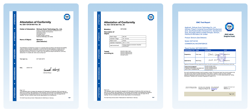
| Attestation | ROHS, CE ,ATEx, IECEx |
| Protect grade | IP66 |
| Explosion-proof mark |
II2 G Ex db IIC T6 Gb II2 D Ex tb IIIC T80°C Db |
FAQ about NFPA 855 Gas Detection Requirements for Battery Energy Storage
Q1: Does CGT‑H2100 satisfy NFPA 855 hydrogen‑alarm set‑point requirements?
A1: Yes. Factory high‑alarm point is 25 %LEL, consistent with the NFPA 855 threshold to activate ventilation and safety responses. The low‑alarm 10 %LEL provides early pre‑warning before hazardous concentrations build up. Users can adjust parameters via RS485 host tool or infrared remote controller.
Q2: What maintenance is needed for this detector in long‑term BESS operation?
A2: The detector is designed for no‑routine field calibration under normal air‑background conditions. Keep gas‑inlet openings free of dust blockage. After the 15‑year rated sensor life, perform annual accuracy verification with standard gas. Replace the sensor unit if measurement error exceeds specification limits. Note: Thermal‑conductivity sensors will produce large deviation if background gas changes from normal air, requiring recalibration under such conditions.
Q3: How to connect the detector to meet NFPA 855 interlock requirements?
A3: Wire dry‑contact high‑alarm relay output to the BESS or ventilation control unit for automatic emergency‑ventilation triggering. Connect RS485 to the ESS supervisory system for continuous real‑time hydrogen‑concentration logging. On multi‑detector bus networks, enable the 120 Ω termination resistor only on one end‑unit of the daisy‑chain bus. Shielded twisted‑pair cable is required for RS485 wiring with proper shielding‑grounding (ground resistance <4 Ω).
Q4: What environmental limits should be observed?
A4: Operating range:‑40 ℃~+70 ℃, humidity 5‑95 %RH non‑condensing. Avoid heavy dew, liquid splashing, long‑term exposure to high‑concentration alkaline gas or helium. Mount with sensor probe pointing downward to avoid water condensation pooling inside the detector housing.