English
 Español
 Português
 русский
 français
 日本語
 Deutsch
 Tiếng Việt
 Italiano
 Nederlands
 ไทย
 Polski
 한국어
 Svenska
 magyar
 Malay
 বাংলা
 Dansk
 Suomi
 Pilipino
 Gaeilge
 عربى
 norsk
 اردو
 čeština
 Ελληνικά
 Українська
 فارسی
 தமிழ்
 తెలుగు
 नेपाली
 Burmese
 български
 ລາວ
 Latine
 Қазақ
 Azərbaycan
 slovenský
 Македонски
 Lietuvos
 Eesti Keel
 Română
 Slovenski
 Српски
 Afrikaans
 Беларус
 Монгол хэл
 O'zbek
 Sundanese
 Javanese


Product Description
Introduction of ATEX Certified Gas Detector for Hazardous Area
The CGT-CO2000 gas detector is a professionally certified monitoring device tailored for hazardous industrial environments, fully compliant with ATEX, IECEx, CE and ROHS standards. Featuring an explosion-proof design with the marking II 2 G Ex db IIC T6 Gb and II 2 D Ex tb IIIC T80℃ Db, it is applicable to Zone 1/2 hazardous areas, IIA/IIB/IIC gas and dust environments with a temperature range of T1-T6.
Specially developed for energy storage scenarios such as battery cabins, energy storage containers and cabinets, this detector adopts electrochemical sensors and natural diffusion sampling to continuously monitor carbon monoxide (CO) concentrations within the range of 0–2000×10⁻⁶ volume fraction. It supports two-stage alarm thresholds (200×10⁻⁶ low alarm and 500×10⁻⁶ high alarm), delivering real-time, stable and reliable gas leakage monitoring to prevent industrial safety accidents caused by CO accumulation.
Feature of ATEX Certified Gas Detector for Hazardous Area
First, ultra-long service life and maintenance-free performance stand out as its core strengths. The equipped high-precision electrochemical sensor boasts a 10-year service life under normal working conditions, with factory pre-calibration enablingzero daily calibration and zero routine maintenance, greatly reducing post-operation costs and manual workload.
Second, it adapts to harsh working environments perfectly. It operates stably at temperatures from -40℃ to +70℃ and humidity of 5%–95% RH, with an IP66 full-protection rating. The die-cast aluminum alloy shell is dustproof, waterproof and corrosion-resistant, suitable for long-term outdoor and industrial harsh scene operation.
Third, it features flexible and convenient system compatibility. With standard RS485 communication (9600bps) and dual dry contact relay outputs, it supports hand-in-hand networking of up to 32 detectors on a single bus. The built-in 120Ω terminal resistor is optional via jumper settings, enabling seamless data interaction and alarm signal upload with upper-level control hosts.
In addition, intelligent visual indication ensures intuitive operation. Three LED indicator lights clearly display normal operation, fault status and alarm levels, with red flashing for low alarms and steady red for high alarms, achieving efficient on-site status identification.
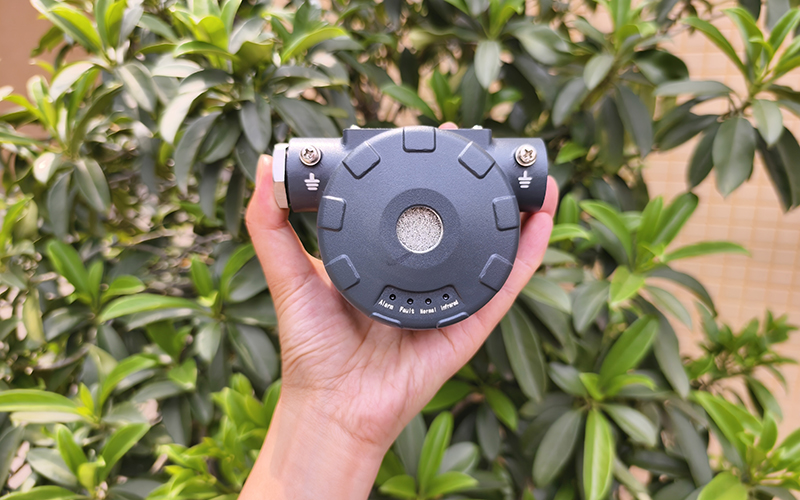
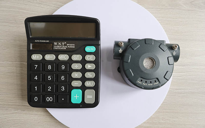
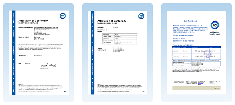
Detail photos of ATEX Certified Gas Detector for Hazardous Area
Product parameters of ATEX Certified Gas Detector for Hazardous Area
| Type | Specific parameters |
| Appearance parameter | |
| Pigment | dark grey |
| Shell material | die-casting aluminium |
| Outline dimension | approximately 100 mm × 78 mm × 53 mm |
| Product weight | approximately 415 g |
| Function parameter | |
| Test gas | CO(carbon monoxide) |
| Sensor type | electrochemical sensor |
| Sample mode | natural diffusion |
| Detection range | (0~2000)×10-6 (volume fraction) |
| Operate mode | continuous monitoring |
| Alarm value setting range (Two-level alarm) |
The minimum alarm threshold for production output is set at 200×10-6 (volume fraction). The maximum alarm threshold for the outlet concentration is set at 500×10-6 (volume fraction). |
| Alarm error | ±50×10-6 (volume fraction) |
| Range indication deviation | allowable error: ±80×10-6 (volume fraction) |
| Alarming light visibility | > 5 m (in darkness) |
| Response time | ≤ 30s |
| Call time | ≤ 15s |
| Resolution ratio | 1×10⁻⁶ (volume fraction) |
| Zero drift range | ≤50×10-6 (volume fraction) |
| Sensor service life | normal monitoring environment for 15 years |
| Electrical parameters | |
| Working voltage | 18VDC-32VDC |
| Rated voltage | 24VDC |
| Power dissipation | ≤ 1W |
| Working current | ≤ 5 mA |
| Alarm current | ≤ 25mA |
| Maximum current | ≤ 25mA |
| Output signal | RS485 (optional) [The communication address defaults to 1 at factory; a built-in 120Ω matching resistor is not connected by default and can be enabled using a jumper cap] |
| Baud rate | 9600 bps |
| Dry contact 1 – Low alarm relay | Group 1: Contact capacity (resistance load): 1A @30VDC; 300 mA @ 125VAC. Factory default: Open during normal operation, close during alarms, open during power loss. |
| Dry contact 2 – High alarm relay | Group 1: Contact capacity (resistance load): 1A @30VDC; 300 mA @ 125VAC. Factory default: Open during normal operation, close during alarms, open during power loss. |
| Indicate way | |
| Pilot lamp | 3 LED status lights |
| State indication | 1. During normal operation: The green indicator light remains illuminated continuously |
| 2. In case of a malfunction: The yellow indicator light remains constantly illuminated. | |
| 3. Alarm indication: When the lower limit is exceeded, a red light flashes; when the upper limit is exceeded, the red light remains on continuously. | |
| 4. During the upgrade process: Red, yellow, and green lights will flash alternately. | |
| Upgrade and configuration parameters | Can be connected to a computer via the RS485 bus (optional) |
| Certification and protection level | |
| Attestation | ROHS, CE ,ATEx, IECEx |
| Protect grade | IP66 |
| Explosion-proof mark |
II2 G Ex db IIC T6 Gb II2 D Ex tb IIIC T80°C Db |
FAQ about ATEX Certified Gas Detector for Hazardous Area
Q1: Does the detector require regular calibration?
A1: No. The device is factory pre-calibrated with zero drift ≤50×10⁻⁶. It supports free calibration and maintenance-free daily use. For long-term operation, annual standard gas testing is optional to verify accuracy.
Q2: What are the key installation and safety requirements?
A2: Installation and commissioning must be completed by professional technicians with power off. The metal shell must be reliably grounded (ground resistance <4Ω), and field cables shall withstand at least 90℃. Live cover opening and operation in dangerous gas environments are strictly prohibited.
Q3: What causes common faults and how to fix them?
A3: Unlit running lights usually result from abnormal power supply or loose wiring; steady yellow fault lights indicate unstable power supply or device damage; communication failures are mainly caused by reversed wiring or duplicate addresses. Users can troubleshoot wiring and power supply first, and replace the device if internal damage occurs.
Q4: What environments will damage the sensor?
A4: Avoid prolonged exposure to CO concentration over 2000×10⁻⁶, silicone substances, sulfides, high-concentration organic volatiles, and condensation water. These factors will cause irreversible sensor failure and loss of alarm function.